Merging computer vision with spatial computing redefines how we authenticate identity. By processing biometric data directly at the edge, XR facial recognition bypasses the vulnerabilities of traditional systems, defeating headset occlusion, eliminating cloud latency, and leveraging depth sensors to neutralize 2D spoofing. This transition turns augmented and virtual reality headsets from passive display devices into highly secure, zero-trust analytical tools.
How Do We Deploy ONNX Models at 90 FPS Using Unity Sentis for On-Device Inference?
The leap from standard mobile applications to Extended Reality (XR) introduces a rigid performance ceiling: the 90 Frames Per Second (FPS) benchmark. When rendering at 90 FPS, an XR headset has approximately 11 milliseconds to render a frame. Within this microscopic window, the device must track the user’s head, render the 3D environment, and process camera feeds. If an XR application requires facial recognition, the traditional architecture of offloading this computational heavy lifting to the cloud fundamentally breaks the immersion. By utilizing Unity Sentis and the Open Neural Network Exchange (ONNX) format, developers can shift inference directly onto the headset’s hardware, achieving instantaneous computer vision.
Why Is Edge Computing Replacing Cloud-Based REST APIs in XR?
Historically, developers tackling computer vision tasks relied on cloud-based REST APIs, such as AWS Rekognition or Google Cloud Vision. In a traditional web or mobile app, a latency of 200 to 500 milliseconds is acceptable. In spatial computing, it is a catastrophic failure. If an augmented reality headset captures an image of a person, compresses it, sends it to a cloud server, waits for the neural network to process it, and waits for the JSON response to return, half a second has passed. By the time the AR application attempts to render a virtual nametag or informational overlay over that person’s face, the individual has already moved or walked past the user. The bounding box will appear to float in empty space, destroying the spatial illusion. Edge computing resolves this by moving the neural network directly onto the physical device. Modern standalone headsets, equipped with chipsets like the Qualcomm Snapdragon XR2, feature dedicated Neural Processing Units (NPUs) and robust mobile GPUs. Running inference on the edge eliminates network latency, protects user privacy by keeping biometric data entirely on the device, and allows the XR application to function perfectly in offline environments.
How Are Standard Facial Recognition Models Converted for Unity?
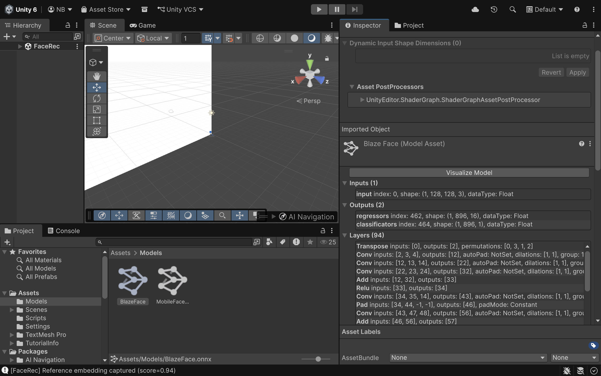
Neural networks for facial recognition, such as MobileFaceNet (optimized for mobile architectures) or RetinaFace (excellent for detecting faces at various scales), are typically trained in Python using frameworks like PyTorch or TensorFlow. Game engines like Unity do not natively run Python code or raw .pt or .h5 model files. The bridge between the data science environment and the spatial computing environment is the ONNX format. ONNX acts as an open standard for machine learning interoperability. A data scientist can train a MobileFaceNet model in PyTorch and export it using a single command: torch.onnx.export(). This encapsulates the model’s architecture, weights, and mathematical operations into a single .onnx file. Once exported, this file is dragged and dropped directly into the Unity asset pipeline. Unity Sentis automatically parses the ONNX file, converting its computational graph into a format the engine can execute.
What Is Model Quantization and How Does It Save Headset Battery?
Even with the ONNX format, a raw neural network might be too “heavy” for a mobile XR headset. By default, most PyTorch and TensorFlow models calculate weights and activations using 32-bit floating-point numbers (FP32). While this offers high precision, it consumes significant memory bandwidth and processing power, which quickly drains the battery of a standalone headset and causes thermal throttling. Model quantization is the process of mapping these continuous 32-bit floats into lower-precision formats, such as 16-bit floats (FP16) or 8-bit integers (INT8). For facial recognition models, moving from FP32 to FP16 often results in a nearly 50% reduction in memory footprint with negligible loss in recognition accuracy. Unity Sentis natively supports these quantized models, allowing the Snapdragon XR2 chip to process the data vastly more efficiently, generating less heat and preserving the headset’s limited battery life.
How Does Unity Sentis Map Inference Tasks to Mobile Hardware?
Unity Sentis operates as a neural network inference library built directly into the engine, bypassing the need for third-party plugins. Its primary advantage is how it handles backend execution. When a developer initializes a Sentis worker, they can specify how the computation should be executed. Sentis can route the ONNX model’s operations to the CPU (using burst compilation for multithreading) or directly to the GPU (using compute shaders). For facial recognition in XR, routing the inference to BackendType.GPUCompute is highly recommended. This leverages the parallel processing architecture of the mobile GPU, rapidly calculating the millions of matrix multiplications required by the facial recognition model without interrupting the engine’s main CPU rendering thread.
How Is an AR Camera Texture Converted into a Multi-Dimensional Tensor?
A neural network does not understand a standard 2D image or a Unity WebCamTexture. It requires mathematical arrays known as Tensors. An image from an AR headset camera must be converted from a sequence of pixels into a multidimensional tensor, typically shaped as [Batch, Channels, Height, Width] or [N, C, H, W]. Unity Sentis provides specialized tools, like the TextureConverter, to handle this pipeline seamlessly. It takes the AR camera feed, resizes it to the specific dimensions the ONNX model expects (e.g., 224×224 pixels), normalizes the RGB color values, and constructs the TensorFloat required for the input layer.
How Is the Inference Script Implemented in C#?
The following implementation demonstrates how to capture a live camera feed, convert it into a tensor, and run it through an ONNX model using Unity Sentis entirely on the device.
using UnityEngine;
using Unity.Sentis;
public class XRFacialRecognition : MonoBehaviour
{
    [Tooltip("The exported ONNX facial recognition model.")]
    public ModelAsset faceModelAsset;

    private WebCamTexture arCameraTexture;
    private IWorker inferenceWorker;
    private TensorFloat inputTensor;
    private Model runtimeModel;
void Start()
    {
        // 1. Initialize the AR Camera feed
        arCameraTexture = new WebCamTexture();
        arCameraTexture.Play();
// 2. Load the ONNX model into Unity Sentis
        runtimeModel = ModelLoader.Load(faceModelAsset);
// 3. Create a Sentis worker, targeting the mobile GPU for maximum performance
        inferenceWorker = WorkerFactory.CreateWorker(BackendType.GPUCompute, runtimeModel);
    }
void Update()
    {
        // Only run inference when a new camera frame is available
        if (arCameraTexture.didUpdateThisFrame)
        {
            ProcessFacialRecognition();
        }
    }
void ProcessFacialRecognition()
    {
        // 4. Convert the WebCamTexture into a TensorFloat
        // Assuming the MobileFaceNet model expects a 112x112 input with 3 RGB channels
        inputTensor = TextureConverter.ToTensor(arCameraTexture, width: 112, height: 112, channels: 3);
// 5. Execute the neural network
        inferenceWorker.Execute(inputTensor);
// 6. Retrieve the output tensor (e.g., facial embeddings or bounding box coordinates)
        TensorFloat outputTensor = inferenceWorker.PeekOutput() as TensorFloat;
// At this point, outputTensor can be read to draw UI over the recognized face
        // outputTensor.MakeReadable();

        // 7. Dispose of the input tensor to prevent memory leaks each frame
        inputTensor.Dispose();
    }
void OnDestroy()
    {
        // Clean up unmanaged Sentis resources when the script is destroyed
        inferenceWorker?.Dispose();
        inputTensor?.Dispose();
    }
}
How Do We Validate Sub-15 Millisecond Execution Times?
Writing the code is only half the battle; validating that the inference does not destroy the headset’s frame rate is the other. Unity’s Profiler is the critical tool for this task. By attaching the Unity Profiler to the standalone build running on the headset, developers can monitor the exact execution time of the Sentis worker.
Because the BackendType.GPUCompute offloads the math to compute shaders, the main thread remains unblocked. If the model has been adequately quantized and the tensor conversions are handled efficiently, the execution time will stay well under the 10-millisecond threshold, guaranteeing that the XR application remains buttery smooth at 90 FPS. Deploying deep learning models directly onto mobile XR hardware represents a fundamental shift in how spatial computing applications handle complex data. By utilizing Unity Sentis to parse ONNX models, developers break free from the latency constraints of cloud APIs. Through proper quantization and efficient tensor management, AR headsets can perform high-fidelity facial recognition entirely locally, ensuring that virtual augmentations lock onto physical targets with zero perceptible delay.
How Does RGB-D Fusion Prevent 2D Spoofing in XR Facial Recognition?
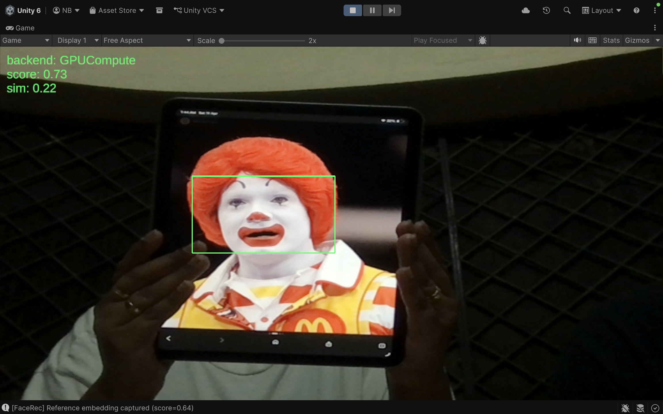
The transition from 2D screens to spatial computing environments fundamentally alters the security paradigm. In standard mobile or desktop applications, facial recognition systems are notoriously vulnerable to “presentation attacks.” A malicious actor can simply hold up a high-resolution photograph or a tablet displaying a video of an authorized user to bypass the system. While software-based “liveness detection” attempts to mitigate this by looking for eye blinks or micro-expressions, it remains a reactive and imperfect defense. Extended Reality (XR) headsets, however, possess a distinct hardware advantage: integrated depth sensors such as LiDAR (Light Detection and Ranging) and Time-of-Flight (ToF) cameras. By fusing the standard RGB color camera feed with a high-fidelity depth map (creating RGB-D data), developers can ensure that the face being scanned is a physical, three-dimensional object with a human-like topological profile, instantly neutralizing 2D spoofing attempts.
What Are the Mechanics of a Presentation Attack?
To understand the solution, one must understand the vulnerability. When a standard neural network processes an image for facial recognition, it flattens the physical world into a grid of pixels. It searches for patterns, contrasts, and distances between key facial landmarks (like the pupils, the tip of the nose, and the corners of the mouth). If an attacker holds up a printed photo of a target, the RGB camera captures those landmarks in the exact same geometric configuration as it would if the actual person were standing there. The computer vision model, devoid of spatial context, calculates the mathematical embeddings, finds a match in the database, and grants access. The system fails because it assumes the 2D representation implies a 3D reality.
How Do Depth Sensors Establish 3D Geometric Verification?
XR headsets constantly map their environment to place virtual objects accurately. They do this by projecting infrared light grids or measuring the time it takes for light pulses to bounce back from surfaces, generating a “depth map.” This map assigns a specific distance value to every pixel. When a face is detected in the RGB feed, the system cross-references that exact bounding box within the depth map. A genuine human face has a highly specific depth signature: the tip of the nose is significantly closer to the camera lens than the cheekbones, and the eyes sit in recessed sockets. Conversely, if an attacker holds up a tablet displaying a face, the depth map will read a completely uniform distance across the entire bounding box. The “face” is perfectly flat. By sampling the depth variance within the recognized bounding box, the XR application can instantly differentiate between a living person and a spoofed surface.
How Do We Align the RGB Frame with the Depth Frame?
The primary technical hurdle in RGB-D fusion is spatial anchor alignment. The RGB camera and the depth sensor on an XR headset are distinct pieces of hardware. They sit at different physical positions on the headset, operate at vastly different resolutions (e.g., a 1080p RGB feed versus a 256×256 depth map), and have different Fields of View (FOV). If a computer vision model draws a bounding box around a face at pixel coordinates (500, 300) on the RGB image, sampling pixel (500, 300) on the depth map will yield completely incorrect data; if that pixel even exists. To solve this, developers must normalize the bounding box coordinates provided by the 2D model into “Viewport Space” (a scale of 0.0 to 1.0). Once normalized, these coordinates can be re-mapped to the specific dimensions of the active depth texture. Furthermore, the engine must account for the physical offset between the camera lenses, applying a transformation matrix to ensure the RGB pixels perfectly align with their corresponding depth values.
How Is Depth Data Extracted Using ARFoundation?
In Unity, extracting this data efficiently requires tapping directly into the device’s CPU image buffers. Relying on GPU readbacks (extracting texture data from the graphics card back to the processor) introduces massive latency, breaking the 90 FPS requirement of XR. Using ARFoundation’s AROcclusionManager, developers can utilize the XRCpuImage API. This allows the application to grab the raw depth data array directly from the sensor in real-time. By isolating the center pixel of the facial bounding box, and surrounding sample points, the script can read the raw floating-point values representing physical distance in meters.
How Is Depth Sampling Implemented in Unity C#?
The following C# script demonstrates how to capture the bounding box of a face detected by a computer vision model, translate its center point into the depth map’s coordinate space, and sample the physical distance to verify 3D geometry.
using UnityEngine;
using UnityEngine.XR.ARFoundation;
using UnityEngine.XR.ARSubsystems;
using Unity.Collections;
using System;
public class DepthSpoofValidator : MonoBehaviour
{
    [Tooltip("Requires an AROcclusionManager component on the XR Camera.")]
    public AROcclusionManager occlusionManager;

    [Tooltip("Maximum allowed depth variance (in meters) to be considered flat.")]
    public float flatSurfaceThreshold = 0.02f;
    /// <summary>
    /// Validates if a detected 2D bounding box corresponds to a 3D physical face.
    /// </summary>
    /// <param name="normalizedBoundingBox">The face bounding box in Viewport space (0 to 1).</param>
    /// <returns>True if 3D geometry is verified, false if it appears to be a flat spoof.</returns>
    public bool ValidateFaceDepth(Rect normalizedBoundingBox)
    {
        // 1. Attempt to acquire the latest environmental depth image directly from the CPU
        if (!occlusionManager.TryAcquireEnvironmentDepthCpuImage(out XRCpuImage depthImage))
        {
            Debug.LogWarning("Depth image not currently available.");
            return false;
        }
        using (depthImage)
        {
            // 2. Define the sample points based on the bounding box
            // We sample the center (nose) and the edges (cheeks/ears)
            Vector2 nosePoint = normalizedBoundingBox.center;
            Vector2 leftCheekPoint = new Vector2(normalizedBoundingBox.xMin, normalizedBoundingBox.center.y);
            Vector2 rightCheekPoint = new Vector2(normalizedBoundingBox.xMax, normalizedBoundingBox.center.y);
            // 3. Extract the depth values at these specific normalized coordinates
            float noseDepth = GetDepthValueAtViewport(depthImage, nosePoint);
            float leftCheekDepth = GetDepthValueAtViewport(depthImage, leftCheekPoint);
            float rightCheekDepth = GetDepthValueAtViewport(depthImage, rightCheekPoint);
            // 4. Calculate the variance. A real face will have a nose closer than the cheeks.
            float depthVarianceLeft = leftCheekDepth - noseDepth;
            float depthVarianceRight = rightCheekDepth - noseDepth;
            // 5. Evaluate against the spoof threshold
            // If the variance is incredibly small, it's likely a flat photo or screen
            if (Mathf.Abs(depthVarianceLeft) < flatSurfaceThreshold &&
                Mathf.Abs(depthVarianceRight) < flatSurfaceThreshold)
            {
                Debug.Log("Spoof Detected: Depth signature indicates a flat surface.");
                return false;
            }
            Debug.Log("3D Face Verified: Natural depth variance detected.");
            return true;
        }
    }
    /// <summary>
    /// Maps a 0-1 viewport coordinate to the depth image array and returns the distance in meters.
    /// </summary>
    private float GetDepthValueAtViewport(XRCpuImage image, Vector2 viewportCoord)
    {
        // Map the 0-1 coordinate to the actual pixel dimensions of the depth image
        int x = Mathf.Clamp(Mathf.RoundToInt(viewportCoord.x * (image.width - 1)), 0, image.width - 1);
        int y = Mathf.Clamp(Mathf.RoundToInt(viewportCoord.y * (image.height - 1)), 0, image.height - 1);
        // Access the raw pixel data from the first plane of the depth image
        XRCpuImage.Plane depthPlane = image.GetPlane(0);

        // Calculate the 1D index for the 2D coordinate
        int pixelIndex = (y * depthPlane.rowStride) + (x * depthPlane.pixelStride);
        // Depending on the device, depth is typically represented as a 32-bit float
        if (image.format == XRCpuImage.Format.DepthFloat32)
        {
            NativeArray<float> depthData = depthPlane.data.Reinterpret<float>(1);
            // The rowStride and pixelStride are in bytes, so we adjust for a 4-byte float
            int floatIndex = pixelIndex / 4;
            return depthData[floatIndex];
        }

        return 0f;
    }
}
What Does Depth Validation Look Like in Practice?
When this script is deployed to an XR headset, the validation process happens entirely in the background, requiring no extra input from the user. However, visually representing this data provides crucial feedback regarding the security state of the application.
How Does RGB-D Fusion Elevate Enterprise Security?
Relying solely on 2D computer vision in a spatial computing environment ignores half of the hardware’s capabilities. By bridging the gap between flat pixel analysis and volumetric spatial data, RGB-D fusion creates a practically unbreachable biometric gateway. An attacker can easily print a photo or record a video, but fabricating a mask with precise, human-accurate sub-millimeter depth signatures in real-time is exponentially more difficult. By mandating that every facial recognition query passes a geometric depth check, enterprise XR applications ensure that their most sensitive data is protected by the unforgeable physical presence of the user.
How Do HMDs Break Standard Facial Recognition Algorithms?
When multiple users operate in a shared physical space wearing Extended Reality (XR) headsets, a unique biometric challenge arises: they cannot visually authenticate one another. Standard facial recognition algorithms, such as FaceNet, ArcFace, or standard VGG-Face architectures, rely heavily on global facial symmetry. They extract hundreds of nodal points across the entire face, calculating precise distances between the pupils, the bridge of the nose, the cheekbones, and the jawline. A Head-Mounted Display (HMD) like the Meta Quest 3 or Apple Vision Pro acts as a massive physical occluder, entirely blocking the top 40% to 50% of the user’s face. When a standard computer vision model attempts to process an image of an HMD-wearing user, it fails to locate the eyes and eyebrows, the most heavily weighted anchors in facial biometrics. The resulting confidence scores plummet, causing the pipeline to either misidentify the user or fail to detect a human face altogether. To maintain seamless, secure interactions in co-located XR environments, the computer vision pipeline must adapt to recognize identity based solely on the data that remains visible.
What Is Periocular Recognition and How Does It Solve Occlusion?
Traditionally, periocular recognition refers to identifying an individual based strictly on the features surrounding the eyes, a technique highly effective when users are wearing surgical masks covering their lower faces. However, for XR applications, developers must deploy an “inverted” periocular pipeline. Because the HMD covers the eyes, the neural network must be trained to establish identity using only the lower face, mouth, and jawline. This specialized approach discards the reliance on interocular distance (the space between the eyes) and instead focuses on a dense extraction of lower geometric landmarks. The pipeline analyzes the precise curvature of the jawline, the width and depth of the philtrum (the groove above the upper lip), the structural topology of the chin, and the spatial relationship between the corners of the mouth. By isolating these specific lower-facial nodal points, the algorithm can establish a highly accurate biometric signature that remains completely unaffected by the presence of a bulky VR or AR headset.
How Are Custom YOLO Models Trained for Partial-Face Scenarios?
Deploying this capability in real-time requires an object detection and feature extraction architecture built for speed, making YOLO (You Only Look Once) an ideal candidate for the mobile processing constraints of an XR headset. However, pre-trained YOLO models are configured for full-face detection. To build a robust pipeline, developers must train custom YOLO networks specifically designed to identify and extract embeddings from partial faces. The primary bottleneck in this process is the dataset. There are very few large-scale, open-source datasets featuring thousands of different individuals wearing various modern XR headsets. If a model is trained exclusively on unoccluded faces, it will fail in deployment. The solution lies in aggressive data augmentation, programmatically altering existing, massive facial datasets (like Labeled Faces in the Wild or CelebA) to simulate the precise occlusion patterns of an HMD.
What Data Augmentation Strategies Simulate Headset Occlusion?
To train the custom YOLO model to ignore the top half of the face and prioritize the jawline and mouth, developers artificially “blind” the training data. This is achieved by creating an automated augmentation pipeline that draws a rigid, opaque mask, typically a black rectangle, over the top portion of every image in the dataset. By applying this transformation during the training phase, the neural network is forced to calculate its loss gradients and optimize its weights based entirely on the lower facial geometry. The network “learns” that the upper portion of the image contains no valuable data (representing the headset) and becomes highly sensitive to the minute, unique details of the lower face.
How Is the Augmented Training Dataset Generated via Python?
To simulate this occlusion accurately across tens of thousands of images, developers utilize computer vision libraries like OpenCV combined with augmentation frameworks like Albumentations. The following Python script demonstrates how to batch-process a folder of pre-cropped facial images, defining a custom Albumentations transform that blacks out the exact top 40% of the image to mimic a generic XR headset.
# 1. Define a custom Albumentations transform to simulate an HMD class SimulateHMD(ImageOnlyTransform): def __init__(self, occlusion_ratio=0.40, always_apply=True, p=1.0): super(SimulateHMD, self).__init__(always_apply, p) # occlusion_ratio defines how much of the top face is covered (e.g., 40%) self.occlusion_ratio = occlusion_ratio
import cv2
import os
import glob
import albumentations as A
from albumentations.core.transforms_interface import ImageOnlyTransform
import numpy as np
# 1. Define a custom Albumentations transform to simulate an HMD
class SimulateHMD(ImageOnlyTransform):
    def __init__(self, occlusion_ratio=0.40, always_apply=True, p=1.0):
        super(SimulateHMD, self).__init__(always_apply, p)
        # occlusion_ratio defines how much of the top face is covered (e.g., 40%)
        self.occlusion_ratio = occlusion_ratio
    def apply(self, img, **params):
        # Retrieve image dimensions
        height, width = img.shape[:2]

        # Calculate the pixel cutoff for the headset occlusion
        occlusion_height = int(height * self.occlusion_ratio)

        # Create a copy of the image to modify
        occluded_img = img.copy()

        # Draw a solid black rectangle over the top section
        cv2.rectangle(occluded_img, (0, 0), (width, occlusion_height), (0, 0, 0), thickness=-1)

        return occluded_img
# 2. Initialize the augmentation pipeline
# We can easily add other augmentations like blur or noise to increase robustness
transform_pipeline = A.Compose([
    SimulateHMD(occlusion_ratio=0.42, p=1.0)
])
def batch_process_dataset(input_folder, output_folder):
    """
    Reads all JPG images in the input folder, applies the HMD simulation,
    and saves the augmented images to the output folder.
    """
    if not os.path.exists(output_folder):
        os.makedirs(output_folder)
    # Grab all image paths in the dataset directory
    image_paths = glob.glob(os.path.join(input_folder, "*.jpg"))
    print(f"Found {len(image_paths)} images. Starting augmentation...")
    for path in image_paths:
        # Read the image using OpenCV
        img = cv2.imread(path)
        if img is None:
            continue

        # Convert BGR to RGB (Albumentations expects RGB)
        img_rgb = cv2.cvtColor(img, cv2.COLOR_BGR2RGB)

        # 3. Apply the custom pipeline
        augmented = transform_pipeline(image=img_rgb)
        aug_img_rgb = augmented['image']

        # Convert back to BGR for saving
        aug_img_bgr = cv2.cvtColor(aug_img_rgb, cv2.COLOR_RGB2BGR)

        # Construct the output path and save
        filename = os.path.basename(path)
        out_path = os.path.join(output_folder, f"hmd_{filename}")
        cv2.imwrite(out_path, aug_img_bgr)
    print("Data augmentation complete. Dataset is ready for YOLO training.")
# Execute the pipeline
if __name__ == "__main__":
    # Ensure these directories exist in your local workspace
    raw_dataset_dir = "./dataset/raw_faces"
    augmented_dataset_dir = "./dataset/hmd_faces"

    batch_process_dataset(raw_dataset_dir, augmented_dataset_dir)
How Do Lower-Face Features Guarantee Identity Verification?
Once the dataset is prepared and the custom YOLO model is trained, the pipeline must successfully extract and compare the remaining features. While the lower face contains less overall surface area than the full face, its geometric landmarks are highly distinctive. The shape of the jawbone, the muscular structure around the lips, and the depth profile of the chin are heavily influenced by underlying bone structure, which remains static over time. By mapping these specific nodal points and generating a high-dimensional vector embedding, the system can cross-reference the user against a secure database with remarkable accuracy. This allows an enterprise worker wearing an AR headset to look at a colleague across the room, instantly bypass the physical occlusion of the hardware, and securely verify their identity via an augmented reality nametag or secure data overlay.
How Does Resolving Occlusion Advance Shared Spatial Computing?
Overcoming the physical occlusion of HMDs is a critical milestone for collaborative spatial computing. If users cannot authenticate the identities of those around them, shared XR experiences remain severely limited in high-security, enterprise, or defense environments. By shifting away from rigid, full-face requirements and engineering an intelligent, inverted periocular pipeline, developers turn a massive hardware obstacle into an algorithmic non-issue. Through targeted data augmentation and custom model training, XR headsets become capable of seeing past the hardware, ensuring that trust, security, and seamless interaction remain intact within the augmented workplace.
How Does Zero-Trust Spatial Computing Utilize Ephemeral Vector Embeddings?
In highly secure enterprise environments, the fundamental architecture of spatial computing introduces a severe compliance risk. Extended Reality (XR) headsets possess multiple outward-facing cameras that continuously map their surroundings at high frame rates. If an engineer wears a headset inside a secure server room, a defense manufacturing plant, or a research lab with proprietary schematics written on a whiteboard, capturing and transmitting raw video feeds to a cloud server for facial recognition is a catastrophic security violation. A zero-trust spatial computing architecture solves this dilemma by strictly guaranteeing that raw image data never leaves the physical device. By leveraging “ephemeral vector embeddings,” the headset can instantly authenticate the identities of individuals in the room using complex mathematical representations, while actively destroying the visual evidence of the encounter within milliseconds.
What Is the Difference Between Face Detection and Face Recognition?
To understand how zero-trust biometric pipelines operate, it is vital to separate the processes of detection and recognition. * Face Detection answers the question: “Is there a face in this frame?” This involves scanning the raw camera pixel data to find shapes that resemble human facial structures and drawing a bounding box around them. * Face Recognition answers the question: “Whose face is this?” This process takes the pixels inside the bounding box and translates them into a unique identifier to establish identity. In a zero-trust XR application, both of these processes must occur entirely on the headset’s local hardware, such as the Snapdragon XR2’s Neural Processing Unit (NPU), without ever invoking an external REST API.
How Do Ephemeral Vector Embeddings Protect Enterprise Security?
When a face is detected by the XR headset, the local neural network (such as a quantized MobileFaceNet model) analyzes the cropped image. Instead of saving the image, the network translates the facial geometry into a Vector Embedding. A vector embedding is an array of floating-point numbers, typically 128 dimensions in size. These 128 numbers represent the geometric and textural features of the face mapped into a high-dimensional latent space. Crucially, it is mathematically impossible to reverse-engineer or reconstruct the original photograph of the person’s face from this array of numbers. Once this 128-dimensional embedding is generated, the concept of “ephemerality” is enforced. The raw RGB camera frame is immediately flushed from the headset’s volatile RAM. The device is no longer holding a picture of a secure facility or an employee; it is only holding a temporary mathematical sequence.
How Does On-Device Processing Eliminate Raw Data Transmission?
With the ephemeral vector held in local memory, the headset must determine if this string of numbers matches an authorized user. The XR application queries an encrypted, locally stored database that resides directly on the headset. This database contains the pre-calculated vector embeddings of all cleared personnel. Because the database only contains arrays of floats, not photographs, it is extremely lightweight and highly secure. Even if the headset is compromised or stolen, a bad actor extracting the local database would only find meaningless columns of decimals, yielding no usable visual data or personally identifiable photographs.
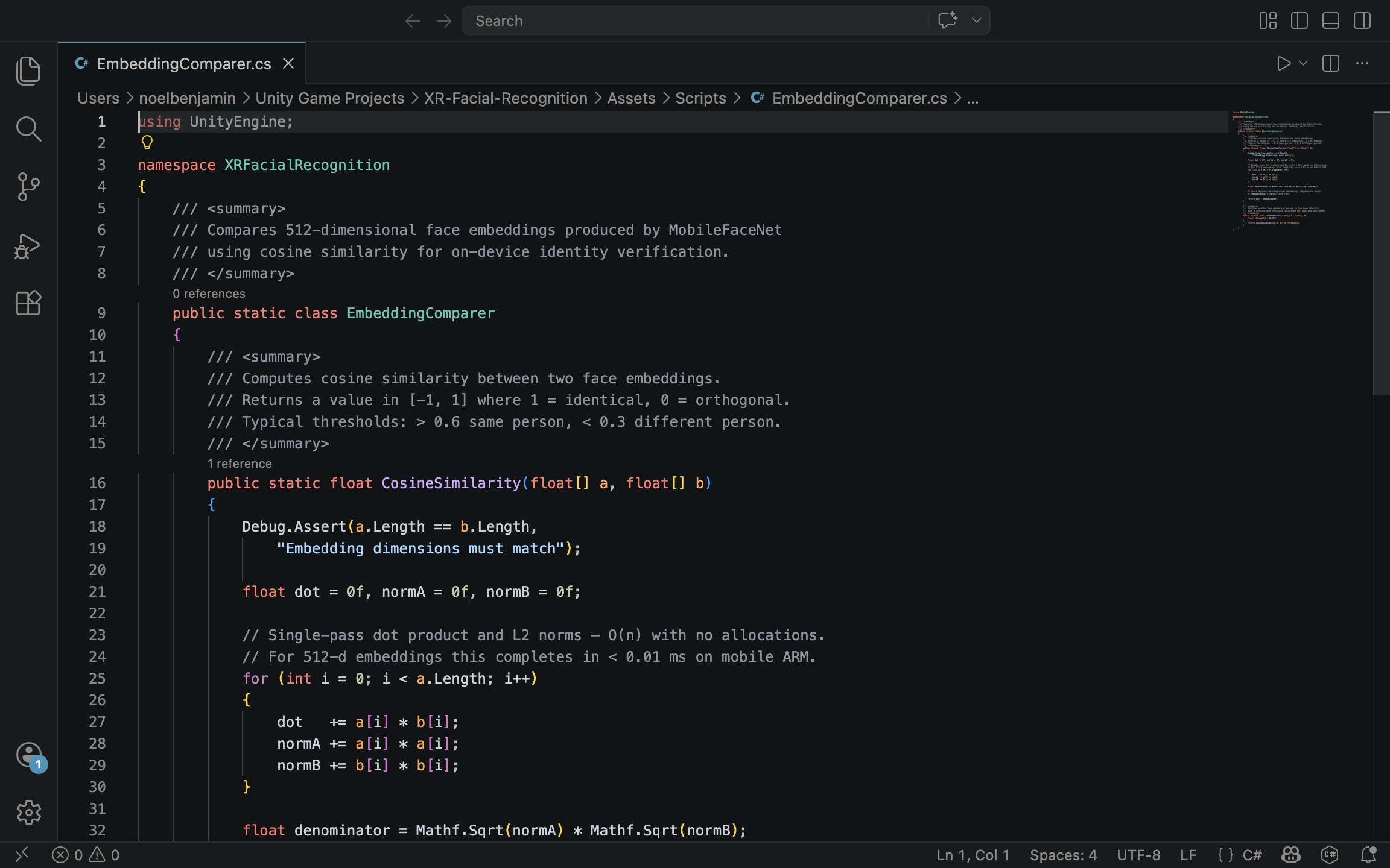
How Is Cosine Similarity Used to Authenticate Identities?
To find a match, the spatial computing application must compare the newly generated ephemeral vector against the vectors in the secure database. Because these embeddings are multi-dimensional spatial representations, they are compared using a mathematical metric called Cosine Similarity. Cosine Similarity measures the cosine of the angle between two non-zero vectors in a multi-dimensional space. The formula is expressed as:
If the two 128-dimensional vectors point in the exact same direction (meaning the facial features are identical), the cosine similarity is exactly . If they are completely unrelated, the value drops. In enterprise facial recognition, a strict threshold, typically around or , is established. If the similarity score between the captured vector and the database vector exceeds this threshold, the identity is authenticated.
How Do You Calculate Cosine Similarity in C#?
Because XR headsets render virtual environments at 90 frames per second, this mathematical comparison must be exceptionally fast. Standard game engines like Unity handle this via optimized C# scripts. The following implementation demonstrates a highly performant method for calculating the dot product and magnitudes of two 128-length float arrays, avoiding unnecessary memory allocations or complex object overhead.
using System;
using System.Runtime.CompilerServices;
public static class ZeroTrustBiometrics
{
    /// <summary>
    /// Calculates the cosine similarity between two 128-dimensional facial embeddings.
    /// Inlined for maximum performance during frame-by-frame execution.
    /// </summary>
    [MethodImpl(MethodImplOptions.AggressiveInlining)]
    public static float CalculateCosineSimilarity(float[] capturedVector, float[] databaseVector)
    {
        if (capturedVector.Length != 128 || databaseVector.Length != 128)
        {
            throw new ArgumentException("Facial embeddings must be exactly 128 dimensions.");
        }
        float dotProduct = 0f;
        float magnitudeA = 0f;
        float magnitudeB = 0f;
        // Execute a fast, unboxed loop to process the 128 dimensions
        for (int i = 0; i < 128; i++)
        {
            float a = capturedVector[i];
            float b = databaseVector[i];
            dotProduct += a * b;
            magnitudeA += a * a;
            magnitudeB += b * b;
        }
        // Prevent division by zero if an empty array is passed
        if (magnitudeA == 0f || magnitudeB == 0f) return 0f;
        return dotProduct / (MathF.Sqrt(magnitudeA) * MathF.Sqrt(magnitudeB));
    }
    /// <summary>
    /// Authenticates a match based on an enterprise security threshold.
    /// </summary>
    public static bool AuthenticateIdentity(float[] liveEmbedding, float[] storedEmbedding, float threshold = 0.75f)
    {
        float similarityScore = CalculateCosineSimilarity(liveEmbedding, storedEmbedding);
        return similarityScore >= threshold;
    }
}
Who Benefits from Zero-Trust XR Architectures?
Implementing ephemeral vector embeddings allows spatial computing to enter spaces where it was previously banned. Defense contractors can use AR headsets to overlay schematics onto fighter jets without violating ITAR (International Traffic in Arms Regulations) compliance. Healthcare providers can utilize mixed reality in surgical theaters while maintaining strict HIPAA (Health Insurance Portability and Accountability Act) compliance, knowing that patient faces are mathematically processed but never visually stored. By separating the mathematical identity of a user from their visual representation, zero-trust architectures transform the XR headset from a potential surveillance liability into a highly secure, privacy-first computing platform.
How Do We Anchor Identity Metadata in Contextual AR?
The successful mathematical identification of a face via an on-device neural network is only half the battle in spatial computing. The “last mile” of the user experience involves visualizing that data. When an enterprise worker looks at a colleague, the system must display the colleague’s identity metadata, such as their name, security clearance level, and departmental role, directly within the physical environment. If this data is anchored poorly, the holographic UI will violently jitter, clip through physical objects, or become unreadable, rapidly inducing motion sickness and destroying the utility of the application. Designing a contextual AR interface requires translating raw, noisy 2D pixel coordinates into a stable, deeply anchored 3D holographic workspace.
How Are 2D Bounding Boxes Translated into 3D World Space?
Computer vision models fundamentally operate in a two-dimensional space. When a model like YOLO or MobileFaceNet detects a face, it outputs a bounding box represented by flat pixel coordinates. For example, (X: 450, Y: 300). However, a Unity or Unreal Engine AR environment operates in a three-dimensional Cartesian coordinate system (X, Y, Z). To bridge this gap, developers must calculate the missing Z (depth) variable. By projecting a ray from the camera’s lens through the 2D screen coordinate and into the virtual reconstruction of the physical world, the system can determine the exact spatial location of the detected face. Unity handles this mathematical projection via functions like Camera.ScreenPointToRay(). When this ray intersects with the spatial mesh generated by the headset’s depth sensors, the exact 3D point is recorded, allowing the application to instantiate a holographic UI panel at the precise physical location of the recognized individual.
What Causes Holographic Jitter, and How Do We Eliminate It?
In real-world conditions, computer vision inference is highly noisy. Changes in lighting, slight head movements, or minor occlusions cause the 2D bounding box to jump by a few pixels every frame. In a flat 2D application, this micro-jitter is barely noticeable. In a stereoscopic 3D environment, a holographic panel snapping instantly to these fluctuating coordinates will vibrate aggressively, creating a highly disorienting and nauseating user experience. To construct a usable enterprise application, this high-frequency noise must be filtered out mathematically. The most effective approach in spatial UI design is the application of damping algorithms, such as Vector3.SmoothDamp or Vector3.Lerp (Linear Interpolation). Instead of forcing the UI panel to instantly teleport to the newest coordinate provided by the CV model, the algorithm acts as a digital spring. It smoothly pulls the UI toward the target coordinate over time. For more complex, predictive tracking, especially when a recognized person walks behind a pillar and temporarily disappears from the camera view. Developers can employ Kalman filters, which calculate the object’s velocity and predict its future trajectory to maintain a flawless UI anchor.
Why Is Billboarding Essential for Spatial UX?
Anchoring a UI panel in 3D space introduces an additional usability challenge: readability from multiple angles. If a holographic panel containing identity metadata is anchored statically above a person’s head, and that person turns 90 degrees to face a different direction, the UI panel will turn with them, leaving the viewer looking at the unreadable, microscopic edge of a 2D canvas. To resolve this, spatial interfaces utilize a technique called “Billboarding.” This algorithm continuously overrides the rotation of the UI panel, forcing its forward-facing axis to perfectly align with the XR camera’s lens. No matter where the target person moves or how they rotate their body, the identity metadata effortlessly pivots to ensure the text remains legible to the headset wearer.
How Is Smooth UI Tracking Implemented in Unity C#?
The following C# script demonstrates a complete pipeline for taking a 2D bounding box coordinate, casting a physical ray to discover its 3D depth, instantiating a holographic canvas, and applying linear interpolation and billboarding to guarantee a smooth, readable user experience.
using UnityEngine;
using UnityEngine.UI;
public class ContextualUIAnchor : MonoBehaviour
{
    [Tooltip("The World Space Canvas Prefab containing the identity metadata UI.")]
    public GameObject identityUIPrefab;

    [Tooltip("How quickly the UI catches up to the target. Lower is smoother but slower.")]
    public float trackingSmoothness = 8f;

    [Tooltip("Layer mask representing the physical environment (AR Mesh).")]
    public LayerMask spatialMeshLayer;
    private GameObject activeUIInstance;
    private Camera xrCamera;
    void Start()
    {
        // Cache the main XR camera for performance
        xrCamera = Camera.main;
    }
    /// <summary>
    /// Call this function every frame the CV model outputs a detected face coordinate.
    /// </summary>
    /// <param name="screenCoordinate">The center of the 2D bounding box.</param>
    public void UpdateIdentityAnchor(Vector2 screenCoordinate)
    {
        // 1. Instantiate the UI panel if it does not already exist
        if (activeUIInstance == null)
        {
            activeUIInstance = Instantiate(identityUIPrefab);
        }
        // 2. Cast a ray from the 2D pixel coordinate into the 3D environment
        Ray projectionRay = xrCamera.ScreenPointToRay(screenCoordinate);

        if (Physics.Raycast(projectionRay, out RaycastHit hitInfo, 10f, spatialMeshLayer))
        {
            // Calculate the target position slightly above the hit point (e.g., above the head)
            Vector3 targetPosition = hitInfo.point + new Vector3(0f, 0.3f, 0f);
            // 3. Apply Lerp to smoothly transition the UI to the new position, eliminating CV jitter
            activeUIInstance.transform.position = Vector3.Lerp(
                activeUIInstance.transform.position,
                targetPosition,
                Time.deltaTime * trackingSmoothness
            );
            // 4. Apply Billboarding to ensure the UI always faces the XR headset
            // We use LookAt with the camera's forward vector to prevent the UI from flipping upside down
            activeUIInstance.transform.LookAt(
                activeUIInstance.transform.position + xrCamera.transform.rotation * Vector3.forward,
                xrCamera.transform.rotation * Vector3.up
            );
        }
    }
    /// <summary>
    /// Hides the UI when the face is no longer detected by the CV model.
    /// </summary>
    public void ClearIdentityAnchor()
    {
        if (activeUIInstance != null)
        {
            Destroy(activeUIInstance);
            activeUIInstance = null;
        }
    }
}Who Ultimately Benefits from Optimized AR UI?
Perfecting the spatial user interface is what transforms a highly complex machine-learning pipeline into an invisible, effortless tool. When the jitter is mathematically smoothed and the holographic text dynamically aligns to the viewer’s gaze, the technology fades into the background. Law enforcement officers, security personnel, and enterprise administrators no longer have to struggle to interpret fluctuating data feeds; they are simply presented with stable, contextually relevant information exactly where they need it. A sophisticated tracking and rendering pipeline guarantees that the cognitive load on the user remains minimal, allowing them to focus entirely on their real-world environment and the physical individuals within it.
Facial recognition in spatial computing requires fundamentally re-engineering how we process biometric data. By shifting neural inference to the edge, fusing RGB with depth maps to eliminate spoofing, and enforcing zero-trust ephemeral pipelines, developers can overcome the strict performance and privacy constraints of modern headsets. Ultimately, when anchored by stable, context-aware interfaces, XR facial recognition transitions from a theoretical security vulnerability into a seamless, indispensable tool for collaborative enterprise environments.